This section describes the Fast Input concept with Pipe Network motion engine, as well as how they can be used in your applications.
What are Fast Inputs?
Fast inputs allow a high-speed application to get position information about the occurrence of an external event at a higher resolution than the cycle time. Thanks to the precise timing of external events, an application can improve its control algorithm, resulting in higher operating performance. Fast (or high-speed) inputs are digital inputs of a drive that are configured to latch the time at which they are triggered.
The time capture can be triggered either by the positive (rising) edge or by the negative (falling) edge of the digital input. Note that it is also possible to configure a Fast InputThe inputs are taken into account at each cycle depending on the system periodicity (for example each millisecond). Under certain circumstances this can be insufficient when more accuracy is needed, or if a quick response is required from the system. To fill the gap, a drive may have some Fast Input connections (generally one or two). When an event happens that triggers a Fast Input (e.g. when a sensor sends a rising edge), the detection of a signal occurs faster (which can be 1000 times more accurate than the system periodicity). Then the timestamp associated with this input can be provided to the IPC to take corrective action to latch the motor position instead of latching the time (see "AKD Drive"). However, when working with KAS, time latching is more useful, because the positions of all the drives in the application can then be interpolated by means of the Trigger block with the MLTrigReadPos function block. As a consequence, we assume in the procedures described below that Fast InputsThe inputs are taken into account at each cycle depending on the system periodicity (for example each millisecond). Under certain circumstances this can be insufficient when more accuracy is needed, or if a quick response is required from the system. To fill the gap, a drive may have some Fast Input connections (generally one or two). When an event happens that triggers a Fast Input (e.g. when a sensor sends a rising edge), the detection of a signal occurs faster (which can be 1000 times more accurate than the system periodicity). Then the timestamp associated with this input can be provided to the IPC to take corrective action are configured to latch the time.
Only digital inputs 1 and 2 can be used as Fast Inputs.
When using both fast inputsThe inputs are taken into account at each cycle depending on the system periodicity (for example each millisecond). Under certain circumstances this can be insufficient when more accuracy is needed, or if a quick response is required from the system. To fill the gap, a drive may have some Fast Input connections (generally one or two). When an event happens that triggers a Fast Input (e.g. when a sensor sends a rising edge), the detection of a signal occurs faster (which can be 1000 times more accurate than the system periodicity). Then the timestamp associated with this input can be provided to the IPC to take corrective action on one axis, a custom .XML"Extensible Markup Language " XML is a general-purpose markup language. It is classified as an extensible language because it allows its users to define their own tags file is required. Contact Kollmorgen.
When using S300"Servostar 300 drive" See Servo Drive in Glossary or S700"Servostar 700 drive" See Servo Drive in Glossary, Fast input has to be enabled by setting the drive keywords IN1MODE to 26 and IN2MODE to 26. This can be achieve using DriveGUI configuration tool.
Distributed ClockClock signal
When the input is triggered, the timestampA timestamp is a sequence of characters, denoting the date and/or time at which a certain event occurred is latched. With EtherCATEtherCAT is an open, high-performance Ethernet-based fieldbus system. The development goal of EtherCAT was to apply Ethernet to automation applications which require short data update times (also called cycle times) with low communication jitter (for synchronization purposes) and low hardware costs, the timestamp sent to the KAS IDE"Integrated development environment" An integrated development environment is a type of computer software that assists computer programmers in developing software. IDEs normally consist of a source code editor, a compiler and/or interpreter, build-automation tools, and a debugger via the MLAxisTimeStamp or MLTrigReadTime function blocks is based on the distributed clock that manages the reference clock (for more details on this concept, Distributed Clock (Synchronization)). The KAS IDE converts this timestamp into a relative offset inside the cycle.
The AKD drive has two capture engines which can be freely linked to any input. These high speed inputs can be used in application which, when triggered, caused a drive position to be captured and reported back to the controller.
However, KAS requires that the parameters MLFI_FIRST and MLFI_SECOND correspond to the physical Fast Inputs 1 and 2. Therefore, the AKD must be configured in order to link the fast inputThe inputs are taken into account at each cycle depending on the system periodicity (for example each millisecond). Under certain circumstances this can be insufficient when more accuracy is needed, or if a quick response is required from the system. To fill the gap, a drive may have some Fast Input connections (generally one or two). When an event happens that triggers a Fast Input (e.g. when a sensor sends a rising edge), the detection of a signal occurs faster (which can be 1000 times more accurate than the system periodicity). Then the timestamp associated with this input can be provided to the IPC to take corrective action 1 with the engine 0 and the fast input 2 with the engine 1. The configuration is achieved by setting the drive parameters with the AKD GUI"Graphical User Interface" A GUI is a type of user interface which allows people to interact with a computer and computer-controlled devices View (AKD Drive for more details), or by using SDO write FB in the application program.
Code Example
CASE StepCounter OF

0:

MLAxisRstFastIn(PipeNetwork.Feeder,MLFI_FIRST);

MLAxisMoveVel(PipeNetwork.Feeder,250.0); //Jog Feeder Axis to search for sensorA sensor is a type of transducer that converts one type of energy into another for various purposes including measurement or information transfer input

StepCounter := 1;

1:

IF MLAxisIsTrigged(PipeNetwork.Feeder,MLFI_FIRST,MLFI_RISING_EDGE)
   THEN MLAxisAbs(PipeNetwork.Feeder,MLAxisCmdPos(PipeNetwork.Feeder)); //Stop motion when sensor is reached

   StepCounter := 2;

END_IF;

2:

IF MLAxisGenIsRdy(PipeNetwork.Feeder)
   THEN MLAxisWritePos(PipeNetwork.Feeder,0); //Set Feeder Axis position to zero

   StepCounter := 3;

END_IF;
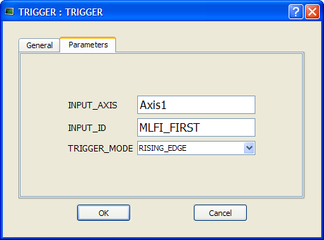
The trigger block is configured using its Properties dialog.
Figure 11-1: Configuration of the Trigger Block
| Function | Description |
|---|---|
| INPUT_AXIS | Defines the axis whose Fast Input is used. This name is the same given to the corresponding axis block in the Pipe Network |
| INPUT_ID | Indicates which one of the two available Fast Inputs in that particular axis is used. The value can be MLFI_FIRST or MLFI_SECOND for the trigger block to be triggered on the arrival of the first or the second input respectively. Specify one of the following constants: MLFI_FIRST or MLFI_SECOND for the trigger block to be triggered on the arrival of the first or the second input respectively. |
| TRIGGER_MODE | Indicates if the trigger block responds to the rising edgeA rising edge is the transition of a digital signal from low to high. It is also called positive edge or the falling edge of the Fast Input Specify one of the following constants: MLFI_RISING_EDGE or MLFI_FALLING_EDGE |
This use case explains how to use the motion library functions of the axes when you want to detect the positive edge of the first Fast Input in the drive, and read its associated timestamp.
The sequence of calls is as follows:
This use case explains how to use the motion library functions of the trigger block, which allows an application to get the position at any point in the Pipe Network when a Fast Input is triggered. It is done by using the timestamp received and interpolating the position of the Pipe Network at that precise time.
Since timestamps of a Fast Input are obtained with a delay of some cycles, the correction done to the Pipe Network position with the trigger block is then relative to the cycle when the Fast Input is issued. You can use MLTrigWriteDelay to address this issue.
After configuring the trigger block, the order of calls to its motion library functions is as follows:
You have to correct the position by taking into account the delay due to the number of cycles needed to read the timestamp of the Fast Input. You can use MLTrigWriteDelay to address this issue.
Sometimes the sensor which is linked to the Fast Input introduces a significant delay in the latched timestamp, typically two updates. In such cases, the trigger block has a configurable parameter: the Delay compensation. This parameter allows you to interpolate the position correctly, taking into account the delay of the sensor as follows:
Corrected timestamp: = Fast input timestamp - DelayCompensation
Two function blocks allow you to set and read the DelayCompensation parameter:
Where the time parameter is specified in microseconds.
The timestamp is based on the EtherCAT system time. For this value to make sense, distributed clock must be activated in the drive and in the EtherCAT master.
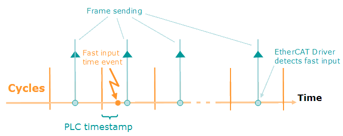
Figure 11-2: PLC Timestamp Related to Fast Input Event
The timestamp returned is relative to the beginning of the cycle in which the Fast Input is triggered. It is called PLC"Programmable Logic Controller" A Programmable Logic Controller, PLC, or Programmable Controller is a digital computer used for automation of industrial processes, such as control of machinery on factory assembly lines. Used to synchronize the flow of inputs from (physical) sensors and events with the flow of outputs to actuators and events timestamp since it is the value that you can use in PLC programs.
|
Stay Connected with Kollmorgen       
|
Copyright © 2015 Kollmorgen™ |

|